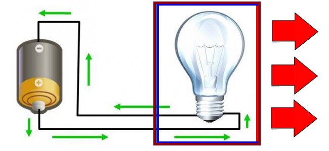
This Christmas Light decoration is a project I conceived many years ago with the idea of having each of the letters that make up the words Merry Christmas light up on its own. The idea originated back when I was in middle school and was based on a simpler project I was working on at the time. This project was built with a small cardboard box, a light that was capable of blinking on and off, and a DC power source. To describe it as simply as possible, this project was built up by drawing the letters of Merry Christmas on one side of the box, then taking a piece of a red plastic bag and lining it across the inside of the side with the letters cut out. Aluminum foil was used to line the remaining sides to reflect the light from the light bulb to make the letters brighter. The light bulb was then wired to a DC power source and placed inside the box. The bulb itself was one of those flashing bulbs that came from a string of lights that go to a Christmas tree, therefore I manage to get the effects of a flashing light using the most basic DC source to light bulb circuit with a switch in between.

Figure 1: Christmas Light Decoration Middle School Diagram
The red arrows indicate desired light direction.
The brown box had the letters Merry Christmas cut into the side lined with red plastic.
This simple project was a marvel to those who observed it functioning at the time and gave me some ideas on how I could make it even more dazzling. I had envisioned separating the letters and lighting them up individually, perhaps in a pattern or some sort. However, at the time, my knowledge of electronics was limited on experiments I did at home and what I learned in my 4th grade science class. I did not know much about the various electronic components and their functions therefore, the idea was put aside for the time being.
Fast forward to my college years and after taking a digital electronics undergrad course I decided to design the Christmas light project that I had envisioned back in middle school. I knew from taking the course that I could achieve the pattern using a binary counter and decoder logic. After considering various circuits for generating the lights beginning with using small incandescent lights, I finally settled on using high brightness LEDs due to their much longer life expectancy and their smaller power requirements. At first I was going to simply implement red LEDs that turn on and off but later decided to include green LEDs that turn on when the red LEDs were off. After some consideration on how I could achieve this I concluded that this could be achieved by simply treating them as logic probes that operate like the off the shelf logic probe devices purchased at electronics stores. The original design consisted of a timer, a binary counter, and a set of gates that provided the decoder logic for one sequence. Given the more powerful capabilities of the Xilinx FPGA device and the use of VHDL to program it, I took this design a step further and added multiple sequences and multiple frequencies for the set of lights. The final design will be covered in greater detail in the following sections.
