|
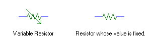
For sake of simplicity, we'll use the schematic symbols for the resistor that varies its resistance (called variable resistors or potentiometers). It looks like this.
|
|
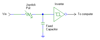
On a PC system, the variable resistor of the joystick, or joystick pot, is wired in series with a capacitor. The voltage value value dropped by the capacitor is converted to a logic binary level (0 or 1), inverted, and sent to the computer. When the voltage is low across the capacitor, the inverter sends a logic 1 (high signal) to the computer. As the voltage increases across the capacitor, the inverter eventually changes the signal to a logic 0 (low signal) after a certain period of time has passed.
|
The high / low values of all four joystick pots (X - Y axes of 2 joysticks) and the status of all four joystick buttons (2 buttons per stick) are sent to the computer via port 201h. The bits of port 201h are made up in the following fashion.
| Port 201h | |||||||
| Joystick Buttons | Joystick Pots | ||||||
| 7 | 6 | 5 | 4 | 3 | 2 | 1 | 0 |
|
* Status is low if button is pressed, high if not. |
|||||||
If we were to simply read the joystick port and look at its bits, it would tell us very little about the state of the joystick pots. That's because the bits themselves only tell us whether or not the capacitors in series with the joystick pots are fully charged. They will tell us also whether or not any of the buttons themselves are pressed. To see how this is done, let's look at some code. These examples assume a little prior knowledge in binary numbers and their hexadecimal equivelent as well as bit manipulation using AND, OR, and NOT operators.