Click the picture for a zoomed in view.
Click here to get the source for the picture.
Whenever I would write games for my old TRS-80, I would have to choose a graphics mode that would provide the best mix of color availability and resolution appropriate for the game itself. Then I would have to make compromises for the memory consumption of the graphics mode and that of the game itself. If the game is fairly complex, oftentimes I would have to select a lower resolution to ensure adequate memory for the program itself.
The PC's don't have this problem because all of the RAM used for text and graphics as well as system BIOS's and (ideally) TSR's are above the conventional 640K of RAM set aside for program and data usage. So no matter what graphics mode or resolution I chose, I would still have the same amount of conventional memory available for my programs. Wow, I really said this! I guess 640K is all the memory I ever needed. :D
The real trade-off in this case is, however, speed. Speed at which the screens can be rendered is very crucial to the game's quality. If a particular screen mode has too high a resolution and too many displayable colors, rendering it may take the computer too long which decreases game quality.
Well, we could go over every screen mode but to save time and to keep it simple, I decided on the video mode 19 for my programming. This video mode has a 320x200 screen resolution with 256 displayable colors. While this resolution seems small by today's standards, it is actually very ideal for video games. Not anymore, but hey, one byte per pixel is rather convenient.
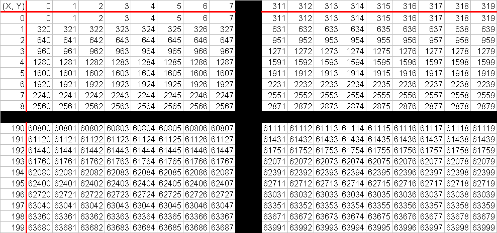
The biggest reason for choosing this particular mode is the case of rendering pixels on the screen. Because the pixel layout is linear, setting a pixel is as easy as writing a byte to a memory location. This diagram below helps illustrate the layout of pixels in memory:

At first glance, this looks somewhat like a multiplication table. This is a grid with each box representing a pixel and the number inside representing a byte position in memory, relative to pixel coordinates (0, 0). Each pixel consumes one byte so setting a pixel coordinate to its appropriate color value involves merely writing that color value to its appropriate address in memory.
Notice the Y axis and how the first pixel of the Y axis is a multiple of 320. Notice also that for each pixel down the X axis, the number inside the boxes increases by 1. Hmm... I see a formula here. A formula that determines byte location given the X and Y coordinates. On VGA screen mode 19, the first byte of display memory is at memory address A000016 or 655360. So to get the memory address for pixel coordinates (5, 10), let's see:
     X = 5                           ' X coordinate
     Y = 10                          ' Y coordinate

     MemAddr = 655360 + 320Y + X     ' Our memory address formula
     MemAddr = 655360 + 320(10) + 5  ' Replace variable with their values
     MemAddr = 655360 + 3200 + 5     ' First multiply
     MemAddr = 658565                ' Then add for final total
To set pixel coordinate (5, 10) with the color code 2, we would just simply load memory location 658565 with 2.
Now that we understand the pixel layout of this video mode, the next thing (or shall I say the first) we need to do is set the VGA card to display this video mode. After all, what good will it do to write pixels in the video buffer RAM if we cannot see this buffer on the screen?